- CEEU conformity
- ISO 9001:2015TÜV SÜD certified
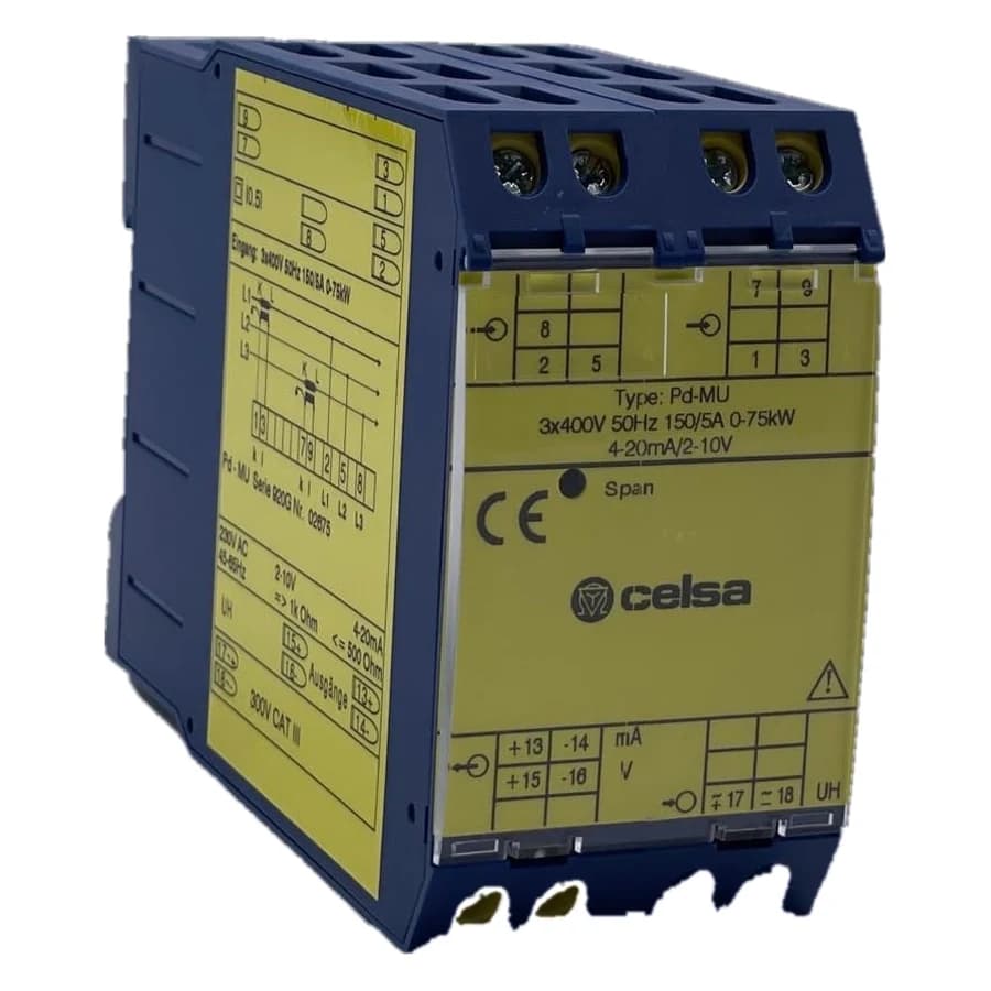
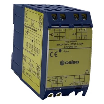
Pdr-MU
Active power
This product is available on request only – we will quote price and delivery time.
- CEEU conformity
- ISO 9001:2015TÜV SÜD certified
Product description
Application
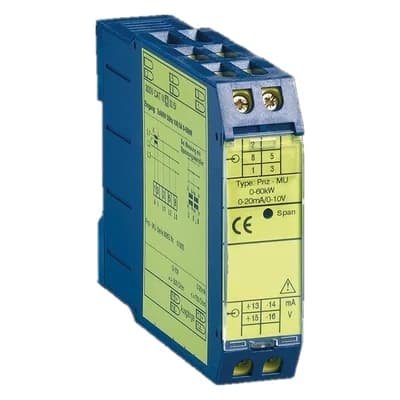
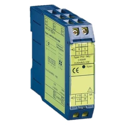
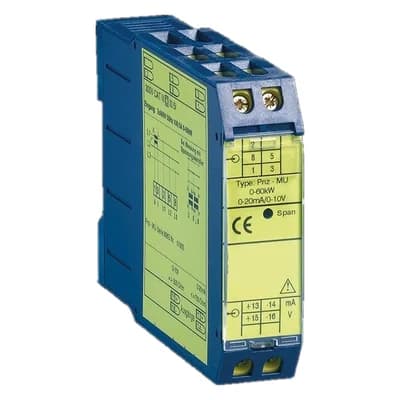
The Pw-MU, Pnz-MU, Pz-MU, Pd-MU and Pdr-MU measuring transducers are used to convert and separate the active power in AC or three-phase networks into an impressed DC current and DC voltage signal.
Function
The quantities to be measured reach the analog multiplier via internal current transformers and voltage dividers. Here, the instantaneous values of current and voltage are multiplied and, in a subsequent integration stage, formed as the mean value of a DC voltage corresponding to the active power. Sinusoidal as well as non-sinusoidal AC quantities of any waveform can be measured. The galvanic isolation between the input and output signals is achieved by means of optocouplers. The downstream amplifiers supply the impressed DC current and DC voltage signals. Both outputs are open-circuit and short-circuit proof.
A connection between both outputs is not allowed. An auxiliary voltage is required for "live zero" or fluctuating nominal voltage of >± 20%.
- Measuring type
- 4-wire three-phase current
- Load
- uneven load
General data
| Dimensions | Housing B, (45 mm wide) Side A1 |
| Weight | 370 g |
Input
| Input variable | active power with alternating or three-phase current |
| Nominal values | |
| - apparent power | 50-150 % of apparent power |
| - alternating current | S = U x I |
| - three-phase current | S = U x I x 1,732 |
| Rated voltage | 100 V, 110 V, 230 V, 400 V, 500 V oder 600 V ± 20 %, max. 3,5 VA |
| Rated current | 1 A oder 5 A, 0,3 VA |
| Rated frequency | 50 Hz, 60 Hz or 400 Hz |
| Overload continuous | |
| - Current | 2-fold |
| - Voltage | 1.2-fold |
| Surge overload | |
| - Current | 20-fold, 1 sec |
| - Voltage | 2-fold, 1 sec |
Output
| Output variables | double output |
| Nominal values | 0-20 mA / 500 load and 0-10 V / max. 10 mA loadable |
| Option | "live zero" 4-20 mA / 500 load and 2-10 V max. 10 mA loadable (auxiliary voltage required) |
| Bipolar output | e.g. -20 ... 0 ... +20 mA / 500 load and - 0 ... 0 ... +10 V / max. 10 mA loadable |
| Zero point boost | e.g. 0-10-20 mA / 500 load and 0-5-10 V / max. 10 mA loadable |
Transmission behavior
| Accuracy | ± 0,5 % |
| Voltage influence | < 0.1 % at ± 10 % of nominal voltage |
| Frequency influence | < 0.3 % at 10 Hz frequency change |
| Phase angle influence | < 0.5 % at ± 90 ° |
| Temperature range | -15 °C to +20 °C to +30 °C to +55 °C |
| Temperature influence | < 0.3 % at 10 K |
| Auxiliary voltage influence | no |
| Load influence | no |
| External field influence | no |
| Residual ripple | < 30 mVpp |
| Response time | < 300 ms |
| Open circuit voltage | max. 24 V |
| Current limitation | max. 2-fold in case of overload |
| Test voltage | < 500 V: 4 kV between input, output, auxiliary voltage > 500 V: 5.2 kV between input and output 4 kV input / output to auxiliary voltage |
Auxiliary voltage
| (only for "live zero", fluctuating nominal voltage and voltages > 500 V) | |
| Standard | 230 V AC ± 20 %, 45-65 Hz, 2.5 VA |
| Options | 110 V AC ± 20 %, 45-65 Hz, 2.5 VA 24 V DC - 15 % to + 25 %, 2 W 6-30 V AC + DC, 2 VA 36-265 V AC + DC, 2 VA |
Installation
| Mounting | Snap-on mounting on top hat rail TH 35 according to DIN EN 60 715 |
| Electrical connection | Screw connection max. 4mm² |
- 70005-1306-9 – Pdr-MU @/5A A: 0-20mA und 0-10V @kW @V (ohne Hilfsspannung)
- 70005-1307-9 – Pdr-MU @/1A A: 0-20mA und 0-10V @kW @V (ohne Hilfsspannung)
- 70005-1308-9 – Pdr-MU @/5A A: 4-20mA und 2-10V @kW @V UH: 230V AC
- 70005-1309-9 – Pdr-MU @/1A A: 4-20mA und 2-10V @kW @V UH: 230V AC /Alternative zu CPR/3NV/I
- 70005-1310-9 – Pdr-MU @/5A A: 4-20mA und 2-10V @kW @V UH: 24V DC
- 70005-1311-9 – Pdr-MU @/1A A: 4-20mA und 2-10V @kW @V UH: 24V DC
- 70005-1319-9 – Pdr-MU @/1A A: 4-20mA und 2-10V @kW @V UH: 24V DC
- 70005-1321-9 – Pdr-MU @/1A A: 4-20mA und 2-10V @kW @V UH: 24V DC